Does your 90s Toyota Celica / Camry / MR2 with a 2.2L 5S-FE sometimes stall out for no reason? Does it crank without starting up? Is it failing to send spark to the spark plugs when it should? Does the check engine light flash a code 12 (1 long 2 short)? Here's what you need to check.
Preliminary checks
Check for spark
The ECU should be triggering the igniter (a small metal box in the engine bay) to send spark to the distributor when the appropriate piston is in the right spot. You can check that a spark plug is getting the spark "signal" in three ways:
Method #1 - Pulling the spark plug out
This only requires a socket set and a helper.
- Disconnect one of the spark plug leads from the spark plug - Grab the silicone / plastic on the top of the engine and pull upwards
- Using a spark plug socket, unscrew the spark plug and pull it out. If the spark plug doesn't come out, but you can feel it "skipping" or "jumping" on the thread, use a magnet or a long "grabby" thing to pull it out.
- Reconnect the spark plug by pushing the rounded end back into the spark plug lead - while the spark plug is out of the engine.
- While holding the spark plug by the lead, ask someone to try to start the car. Since the spark plug makes a circuit through the lead, the centre of the plug, the tip, the gap, the body (thread) and finally to the motor, you can replicate this by holding the plug to a metallic part of the engine.
- While the motor is cranking (being turned over by the starter), you should be able to see a spark or small flash at the tip of the plug. If you don't, skip to the next point. If you do see spark, then put the plug back in. If it still doesn't fire up, then this guide won't help.
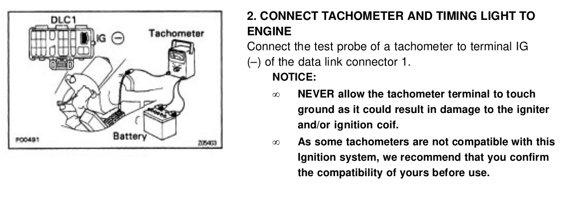
Method #2 - Using a timing light
A timing light is a reasonably simple electronic servicing tool that most auto stores should have. Make sure you're using one that you can confirm works - i.e. test it on a known good car first, or test it when your car is working. You'll also need an assistant.
- Connect the timing light to your battery
- Connect the "sensor" for the light to the first (closest to the belt) spark plug
- Crank the engine while holding down the "trigger" on the light.
- The light should flash once every two rotations, which turns out to be about once per second while cranking. If you don't, skip ahead. If you do see flashes, this guide isn't for you.
Method #3 - Official Method
This is similar to method #2, except using a signal that the ECU generates to trigger the light.
- Connect a light or sensor or oscilloscope to the IG pin on the "check" (diagnostics) connector.
- Crank the car - you should observe the signal pulsing.
- If you don't see the pulses, proceed.
Check for Code #12
The ECU, while not being an OBD-II compliant model, does have early diagnostics present. However, the diagnostics data is cleared when the battery is pulled. Make sure that you've cranked the engine for at least 2 or 3 seconds, while it's exhibited this issue, since you last disconnected the ECU or battery.
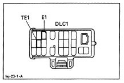
- Connect a piece of wire (breadboard wire or a paperclip works fine here) between the TE1 and E1 pins on the diagnostics connector. This is mounted just behind the left strut tower on the ST204 (6th gen) Celicas.
- Go back into the interior, turn the key into the ON position, and watch the check engine light. It will flash out a code - first it will flash a number of times that is the "tens", then pause, then for the "ones". This guide applies only if you see one flash, a pause, and then two flashes, meaning a code 12. There will be a longer pause between codes, and the codes will repeat once the last one is shown.
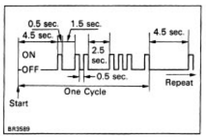
If the light just flashes at a steady pace, then there's no codes stored. Try starting the engine, giving it a few seconds to try and start. If there's still no codes, this guide might not apply to you. If you see a code 12 or 13, proceed.
Code 12 means either:
No NE signal to ECM within 2 sec. or more after cranking.
No G signal to ECM for 3 sec. or more with engine speed between 600 rpm and 4,000 rpm.
This is the ECU saying "I can't see the distributor, so I'm not sure where the engine is, so I can't send a spark"
Code 13 means any of the following:
No NE signal to ECM for 0.3 sec. or more at 1,500 rpm or more.
No G signal to ECM while NE signal is input 4 times to ECM when engine speed is between 500 rpm and 4,000 rpm.
No NE signal to ECM for 0.1 sec. or more at 1,000 rpm or more.
NE signal does not pulse 12 times to ECM during the interval between G1 and G2 pulses.
I think Code 13 will put the ECU into a "limp" mode, so this would be more like "I can't see exactly what I want from the distributor but I'm able to keep the engine running with what I've got".
This guide is specifically for Code 12, but there's a good chance it will apply to some Code 13 situations.
Possible causes
We know from the lists above, that 12/13 related to the NE and G signals. These signals relate specifically to the distributor.
A quick refresher:
Cars made without electronic (computer) ignition were very simple:
- A coil would charge up a high voltage
- The distributor would select which spark plug to send the charge to
- The points in the distributor would send the spark at the precise time
Cars made with "more modern" computerised systems:
- Use a Cam and Crank angle sensor to tell the ECU "where" the engine is at any one time, using markings or teeth on the crank and cams.
- The ECU sends a signal to the appropriate spark plug's "pack" at the right time - replacing the points and the distributor.
- The pack on the spark plug sends the spark to the plug.
These 5S-FE cars are a hybrid:
- The coil is replaced by an "igniter module"
- The distributor still selects the correct cylinder.
- The distributor also has some small generator style "pickup coils", which send pulses at particular times to the ECU
- The ECU determines the perfect time to send spark.
To properly diagnose or repair a Code 12, we need to check three main components:
- The Distributor
- The "Ignition / Timing / Engine" wiring harness
- The ECU
Diagnosis
Firstly, check that the connectors involved are all seated properly:
- One connector on the distributor itself:
- This connector has four wires, and is on the front side of the distributor. On the ST204, the cables should point towards the left strut tower (i.e. come out of the harness and go towards the engine)
- This connector is subject to heat, fumes, and vibration, so don't be surprised if it's brittle. Double check the contacts are clean on both the distributor and the wiring harness.
- Check the four wires of this connector aren't frayed, brittle, or damaged in any other way and make sure you're able to follow them into the harness, without joins, splices, cuts etc.
- On the ST204, the four wires should be Yellow, Red, Blue, Black. If you have an ST204 and they aren't this colour, I would be immediately suspicious of the harness.
- Three connectors on the ECU:
- On the ST204, the ECU is located in the cabin, on the transmission / exhaust tunnel between the passenger and driver's footwells. It is accessible by pulling the carpet up in the corner. There are three connectors that all come from the same harness. Ensure they are firmly plugged in. These shouldn't really give you any trouble, but it might be worth visually checking for corrosion on the pins.
Distributor
This needs an Oscilloscope - if you've got one, or an electronics hobbyist friend, read on. Otherwise skip this section for now.
As mentioned above, the distributor contains two coils that pick up on the movement of (probably?) magnets on the rotating shaft. The first coil is connected to NE+ and NE-, and the other to G+ and G-.
When the distributor rotor is ... rotating it will "induce" a current in the coils, which shows as a voltage. There is one magnet and one coil on the G coil, and four magnets with two coils on NE.
Each time magnet comes close, it will cause a positive voltage which rapidly increases, and then once the magnet passes it will switch to a negative voltage which then slowly returns to 0.
This means, when you measure across each pair of NE +/- and G+/-, you should see rapid pulses with minimal dead spots on NE, and one pulse per each four NE pulses on the G coil. The G coil pulses will look roughly the same, but with more dead "air" between them. Something like the below:

If this is all correct, and the engine still doesn't start, then you've ruled out the the distributor at this point.
One thing to note: Our ST204 had an issue with stalling out when hot, or not starting only when the engine is hot. This was the distributor's fault, so make sure you perform these measurements while the issue is occurring.
If you do see an issue - either the signals aren't present, or strong enough, and you've checked your scope settings and probes, then this is at least part of the problem. Replacing the distributor doesn't seem to be particularly uncommon, but part of me wonders how many distributors have been replaced needlessly because of an issue with the other two parts.
Wiring Harness
The wiring harness that connects the ECU to the distributor is specific to the engine, rather than the car. It has an impressive reach:
- AC Compressor
- Alternator
- Vacuum sensor
- Knock sensor on the rear of the engine
- Injectors
- Throttle Position Sensor
- Distributor
- Starter
- Water temperature sensors
- Gearbox reverse & speed sensors
- Battery
- Fusebox
- Igniter
- Diagnostics connector
- HVAC system
- ECU
- Fuel pump relay
- Interior harness
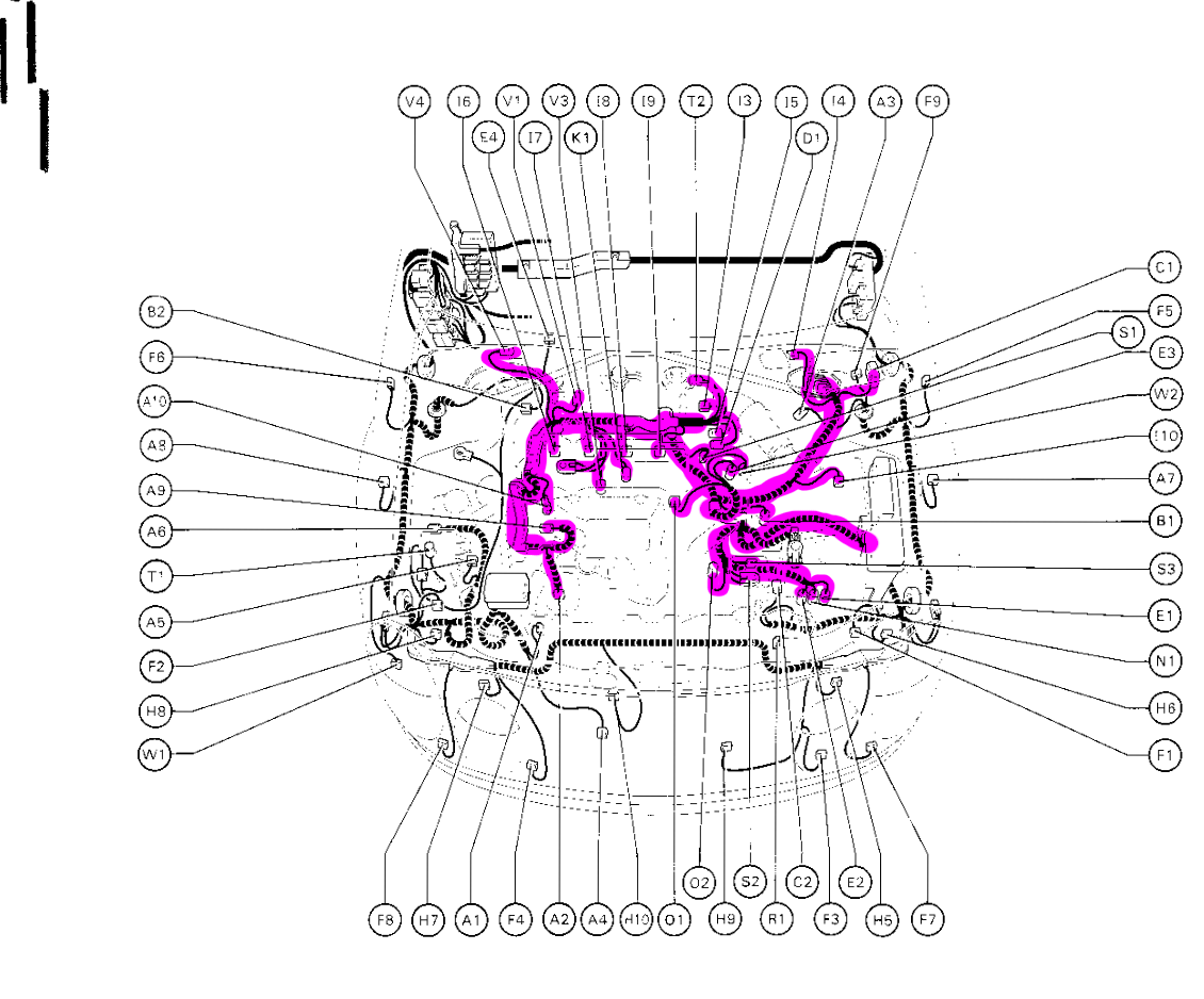
In this case, the part of if that we care about is only:
- Distributor
- Back towards the intake manifold
- Down under the heater core coolant pipes
- Forwards over the gearbox
- Back towards and through the firewall
- Down under the HVAC system
- Into the ECU


Removing the harness to inspect is quite involved, requiring removing a ground from very far behind the engine, so I wouldn't recommend it unless you're prepared to replace it entirely.
Instead, just check that the colours of the harness at both sides match, and that there is good connectivity (use a multimeter in continuity check or resistance check modes) end to end.
You can also check that the signal at the distributor matches the signal at the ECU.
The pins on the ECU are 4,5,17,18 on the largest connector. The pins are numbered from the corner closest to the other connector, and to the latches. 4 and 17 are NE, and 5 and 18 are G:

If the colours match up, there's no obvious damage or alterations, you have continuity, no shorts to ground, and the signal looks good, then you can probably rule out the harness.
Our ST204, in addition to the distributor being a problem when hot, also had a splice in the harness at the distributor end. Someone had replaced the original connector with a compatible one with different colours. The problem was that the splice has been done with solder. This particular location is subject to quite a lot of vibration and heat, so I suspect the solder joins simply became brittle over time. This was causing a problem that got worse and worse that it eventually stopped the car from starting almost all of the time.

I suspect that someone was chasing down an ignition issue, and had replaced the connector as it'd gone brittle. In our case, that replacement connector had also gone brittle while we had the car, and some autoelectricians had replaced it with silicon.
We ended up having to completely replace the harness with one from a wrecked car. This took a few hours each time - I had to remove the original harness, remove the donor harness from the wrecked vehicle, and then install the new harness, so this is not to be done lightly.
The ECU / PCM
The last component on our list is the ECU.
If you're still having issues, and have ruled out the Distributor and Harness, then, as Sherlock Holmes once said, the ECU is the only remaining possibility. Maybe not that exactly.
Removing the ECU is easy - just lift up the carpet behind the stereo / HVAC controls and remove the two bolts on one side and one on the other holding the brackets in. Safely remove the connectors from the ECU and attached relay, and the ECU "lifts" out.
Vehicle manufacturers don't exactly give us ECU schematics, debug headers, debugging symbols or anyting else that would make this part easy. Thankfully, they don't really have to in this case.
Early on in our saga, a mechanic had pointed the blame at the ECU, after replacing the distributor. I'd asked to take a look and see if there was anything I could do to fix the ECU, and they agreed to let me take it home.
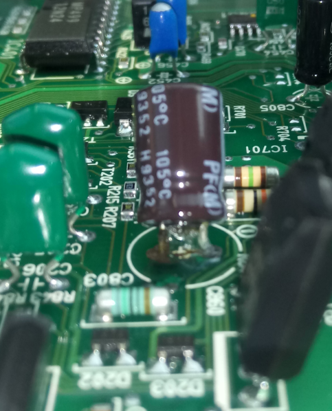
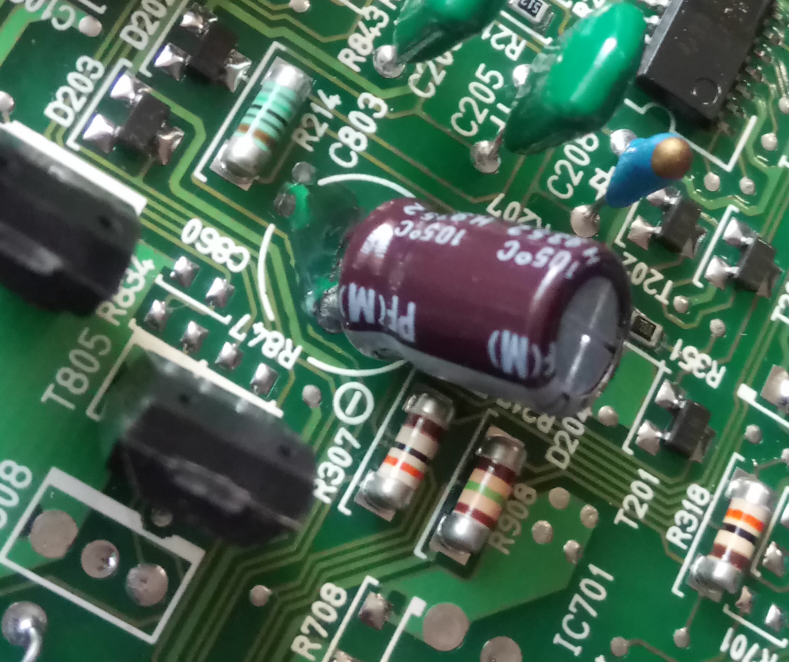
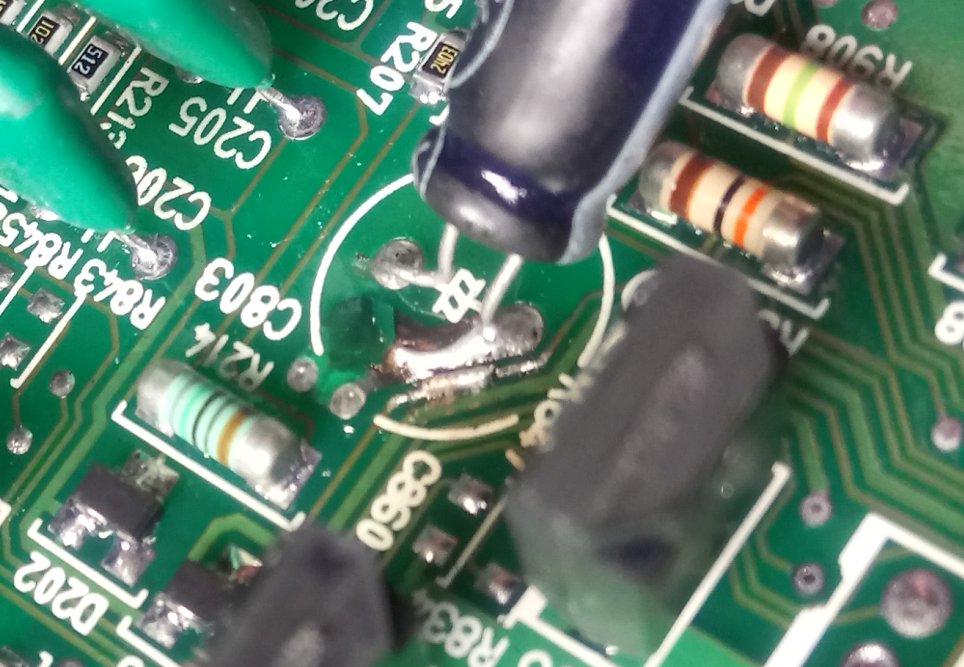
I cracked open the ECU, and found that a capacitor had leaked onto the board:
I could also see some damage to a neighbouring trace:
I removed the capacitor:
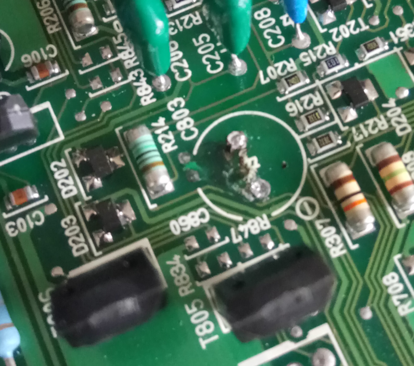
After cleaning up the board, I was able to get a better look at the damage:

If you follow that trace back to the connector, it connects to NE+. Isn't that convenient!
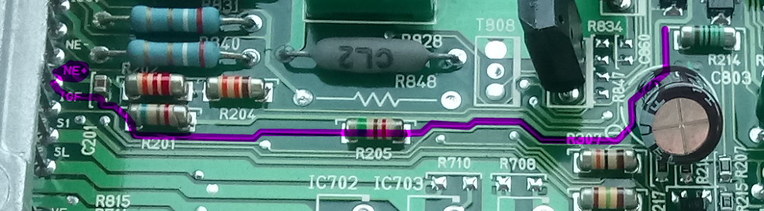
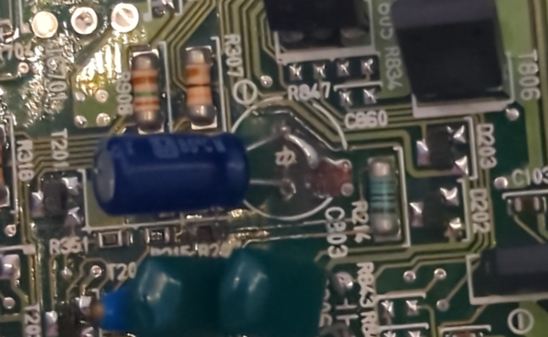
I scratched off the solder mask, and "re-ran" the trace using a thin piece of wire (I re-used the excess leg from a component - the replacement capacitor's excess leg might work here):
That fixed the continuity issue, and the mechanic called me to report that it had fixed the issue! They later called me to say that it hadn't actually fixed the issue, and then replaced the ECU anyway. We would later find out that the wiring harness and distributor were still faulty, so there's a good chance I actually did fix the issue.
The replacement ECU had been repaired in the same way, although arguably less well:
So clearly this isn't a once-off.
We were also contacted by someone on the other side of the country after they'd made a post about their Celica doing very similar things to ours, and their ECU capacitors had left massive black scorch marks on the board!
I would absolutely recommend checking this on any 5S-FE ECU that you come across and fixing it proactively.
The repair
If you're up to it, here's how I repaired it, in broad strokes:
- Use a board cleaner spray to remove the conformal coating (like a nail polish, applied at the factory to prevent corrosion)
- Desolder the capacitor
- Clean the affected area thoroughly with isopropyl alcohol to remove any capacitor electrolyte
- Carefully look for any damage to traces, and repair as necessary
- This might involve just scratching off the solder mask and soldering a wire over the top to re-make that section of the trace.
- You might just have to run a "jumper" from one component on one side of the trace to a component on the other side of the damage - make sure you use thicker wire if the trace is thicker.
- Continuity and drive test the ECU
- Re-apply the conformal coating - this is available in a spray form from Altronics.
- Re-assemble and install the ECU.