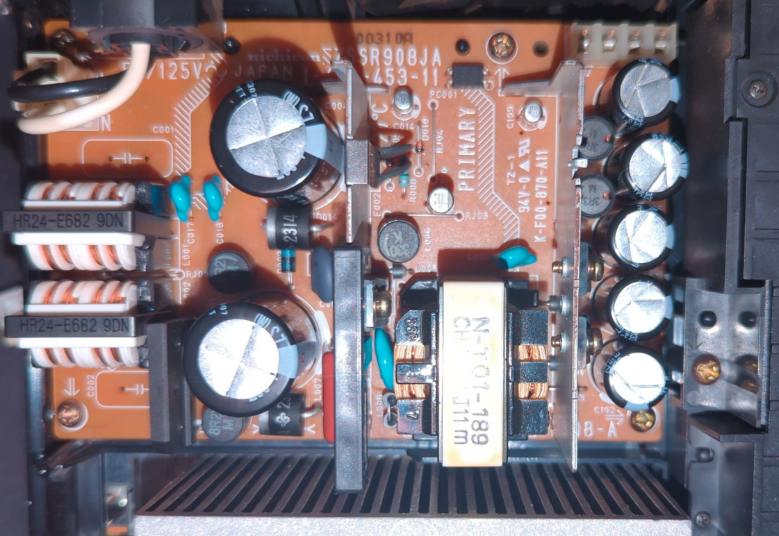
The Sony PlayStation 2 originally launched in Japan first. The first three models are exclusive to Japan, and thus only have 100V capable power supplies.
Thanks to the initial work of Peter Lustig, we were able to confirm that the core of the power supply runs fine on Australian ""230V"" (sometimes 240V) AC power, we just need to upgrade some components.
Warning
This guide involves working with a mains power supply. This means that, at times, up to 250VAC or 360VDC will be exposed.
These voltages will kill you, given the chance.
Only perform these steps if you are sufficiently experienced with electronics.
Ensure that your work space has enough space, and is lit well.
Do not leave exposed AC mains unattended.
Work from a circuit that is protected by an RCD / GFCI.
Ensure you can turn off the power to the device without reaching over it.
Allow the power supply to discharge (by disconnecting the mains input) for at least 30 minutes before touching it.
Metal objects, such as heatsinks, may be live when you don't expect them to be.
You will need:
Tools:
- Philips head screwdriver, size PH2
- A spudger or prying tool (a flat blade screwdriver will suffice) that's small enough to get under the capacitors
- Soldering iron
- Strongly recommended: A temperature controlled one
- Strongly recommended: A beefy one
- Recommended: One with a built in "air intake" to suck some of the fumes up.
- Solder (I used lead-free, flux core)
- Flux (Strongly recommended)
- Good ventilation (Flux is very smoky and very bad for you)
- Desoldering wick or Desoldering station
- Wick works mostly fine, but the large traces will absorb a lot of heat. Don't heat the wick until the solder's flowing.
- Multimeter
- Dummy load or automotive globes
- (Recommended) A non-contact / laser thermometer.
Parts:
Confirmed applicable for the Nichicon ZSSR908JA (Sony P/N: 1-468-453-11).
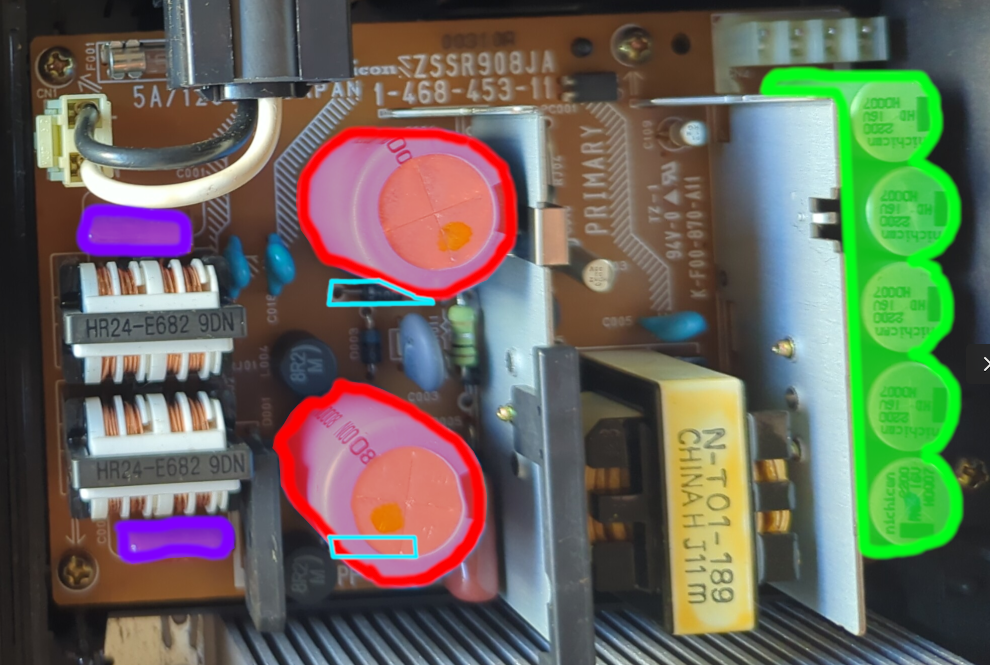
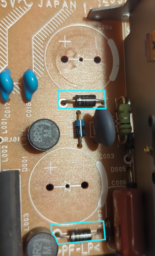
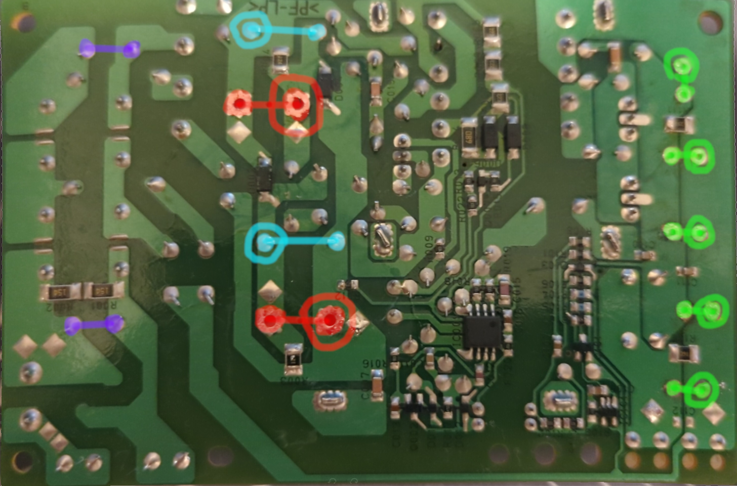
(Negative side of components circled)
- 2x Replacement X-Class mains filter caps. (C001, C002) (Recommended) - shown in purple.
- These reduce the interference sent back into the power grid. Running without these may cause interference with other devices, or upset your power company.
- Existing ones are Nichicon, family QXL or similar
- Type: Film / AC Mains / X-class
- Voltage: 250VAC or greater
- Capacitance: 0.474μF
- Pin pitch: 15mm (with long leads) or 7.5mm (matches hole on board)
- Safety rating: X, X1, X2, or Y, Y1, Y2 (recommended)
- Temperature: 105℃ (Recommended)
- I used two Kemet R463I347050N0M
- 2x Replacement TVSS diodes (D014, D015) (Required) - shown in cyan.
- These diodes are Transient Voltage Surge Suppression - they "short" to keep the voltage below a certain point. These stop your caps going boom on a minor surge.
- Existing: Semitec Z2100 - VBreakdown 100V, VClamping 144V
- Breakdown Voltage: 178V or greater (maximum AC voltage / 0.707 / 2)
- Clamping Voltage: As low as reasonably possible, while still a bit above the breakdown voltage - your mains storage caps should have a higher voltage than these diodes.
- I used two Vishay 5KP160A-E3/54 diodes - they are a bit large and the clamping voltage is higher than I'd like.
- 2x Replacement Mains storage caps (C003, C004) (Required) - shown in red.
- These store the initially converted AC -> DC power ready for the SMPS to cut it up.
- Type: Aluminium Electrolytic Radial
- Voltage: Above your TVSS diode's clamping voltage (ideally), at least 178V
- Capacitance: 330μF or greater
- Diameter: 22.5mm Maximum
- Length / Height: 40mm Maximum
- Pin pitch: 10mm
- Pin type: Snap-in
- Temperature: 105℃ (Recommended)
- To locate replacements, set the above search terms, sort by price, then pick the capacitor that has a good balance of lifetime and ESR.
- I used two Nichicon LLS2E331MELY.
- 5x Replacement output storage caps (C102, C103, C104, C105, C106) (Recommended due to age) - shown in green.
- These store a buffer of power, allowing the PSU to catch up to usage spikes.
- These are at least 24 years old now and are liable to leak.
- Type: Aluminium Electrolytic Radial
- Voltage: 16V minimum
- Capacitance: 2200μF approx
- Diameter: 12.5mm
- Length / Height: 40mm Maximum
- Pin pitch: 5mm
- Pin type: Leads (normal)
- Temperature: 105℃ (Recommended)
- To locate replacements, set the above search terms, sort by price, then pick the capacitor that has a good balance of lifetime and ESR.
- I used five Rubycon 16ZLH2200MEFC12.5X20
Process:
- Disconnect the power from the PS2.
- Wait at least 30 minutes for the mains capacitors to discharge.
- Flip the console over.
- Remove the following screws:
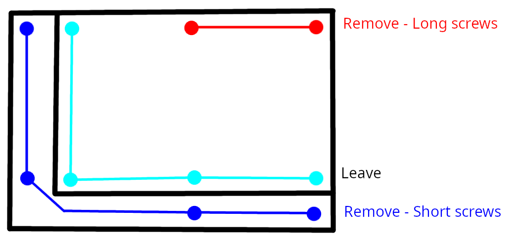
- Remove the Four screws on the "middle" / mezzanine section.
- Remove the Two screws from the very bottom of the unit, closest to the power switch.
- Flip the unit back up.
- Lift the top cover up from the rear, until it's at a ~45 degree angle, then pull it away from the body. Note the front panel switches are still connected. Place the lid next to the unit.
- Remove the four screws holding in the power supply. The Power supply is the board nearest the fan.
- Lift the power supply out. Note that there are some hooks on the disk drive side that you will need to wiggle the board past, and the pins that connect the PSU to the main board may be quite tight. The power supply lifts directly up, once those hooks are cleared.
- Desolder the components we're removing:
- The AC caps can be snipped off and then the legs removed.
- The electrolytic caps (both input and output) sit too close to the board and you will need to desolder them normally. Wick up as much solder as you can, and wiggle the legs with the iron to make sure they are free. You can use the spudger / flat screw driver to pop them out since they'll be hot.
- The big caps will pop out after some resistance.
- The diodes can be snipped, but I just used wick since they're very close to the caps.
- Install the replacement parts:
- The AC caps may need the legs bent to fit in, like how it was done on the original units.
- Solder the diodes before the input caps, making sure the line on the diode is the same side as the line on the diagram.
- Pop-in the input caps and then solder them. As with the diode, the line / negative symbol should be on the side with the thicker line on the part outline.
- Push in the DC caps, and bend their legs out to hold them in. Then solder them normally.
- Test the power supply.
- Attach your multimeter to the output, in 20V mode. The pins closest to corner of the board are negative, the other two positive.
- Safely connect the power supply to AC and turn it on. The multimeter should read 8.5V, or close to. If so, turn off the power supply.
- Next, attach your load to the power supply and turn it on again. If the power supply's voltage is stable, and close to 8.5V, then it should be good to go.
- Check the capacitors and heatsinks with the non-contact thermometer. They shouldn't be super warm.
- Install the power supply in the PS2 again - line up the pins and push the power supply onto them. You might need to wiggle the PSU to get past the hooks.
- Re-install the four screws into the PSU.
- Test the whole unit again, just to be sure.
- Place the top on, reverse of the removal. Line up the front edge, and swing the back half down.
- Flip the unit.
- Re-install the two long screws into the two holes near the power supply / fan.
- Re-install the other four screws in the mid-level.
- Re-install the plugs / feet that cover the screws.
- All done.
