The Sony PSX was exclusively sold in Japan. Naturally, they didn't bother with universal power supplies since that'd add cost.
Based on the work of "Lonedone" on the Assembler games forum, we knew that the power supply of a PSX2 (DESR-x500 or DESR-x700) could be upgraded, but now I've tested and can confirm the same procedure works on a PSX1.
Warning
This guide involves working with a mains power supply. This means that, at times, up to 250VAC or 360VDC will be exposed.
These voltages will kill you, given the chance.
Only perform these steps if you are sufficiently experienced with electronics.
Ensure that your work space has enough space, and is lit well.
Do not leave exposed AC mains unattended.
Work from a circuit that is protected by an RCD / GFCI.
Ensure you can turn off the power to the device without reaching over it.
Allow the power supply to discharge (by disconnecting the mains input) for at least 30 minutes before touching it.
Metal objects, such as heatsinks, may be live when you don't expect them to be.
You will need:
Tools:
- Philips head screwdriver, size PH2
- Tweezers (recommended, metal or high-temp tolerant, flat blade screwdriver can work instead)
- Soldering iron
- Strongly recommended: A temperature controlled one
- Strongly recommended: A beefy one
- Recommended: One with a built in "air intake" to suck some of the fumes up.
- Solder (I used lead-free, flux core)
- Flux (Strongly recommended)
- Good ventilation (Flux is very smoky and very bad for you)
- Desoldering wick or Desoldering station
- Wick works mostly fine, but the large traces will absorb a lot of heat. Don't heat the wick until the solder's flowing.
- Multimeter
- Dummy load or automotive globes
- (Recommended) A non-contact / laser thermometer.
Parts:
Confirmed applicable for the Panasonic ETXNY499J9A (Sony P/N: 1-468-806-11) (PSX1) and Panasonic ETXNY499J9AA (Sony P/N: 1-468-869-11) (PSX2).
If you have a Nichicon PSU, this probably won't apply at all.
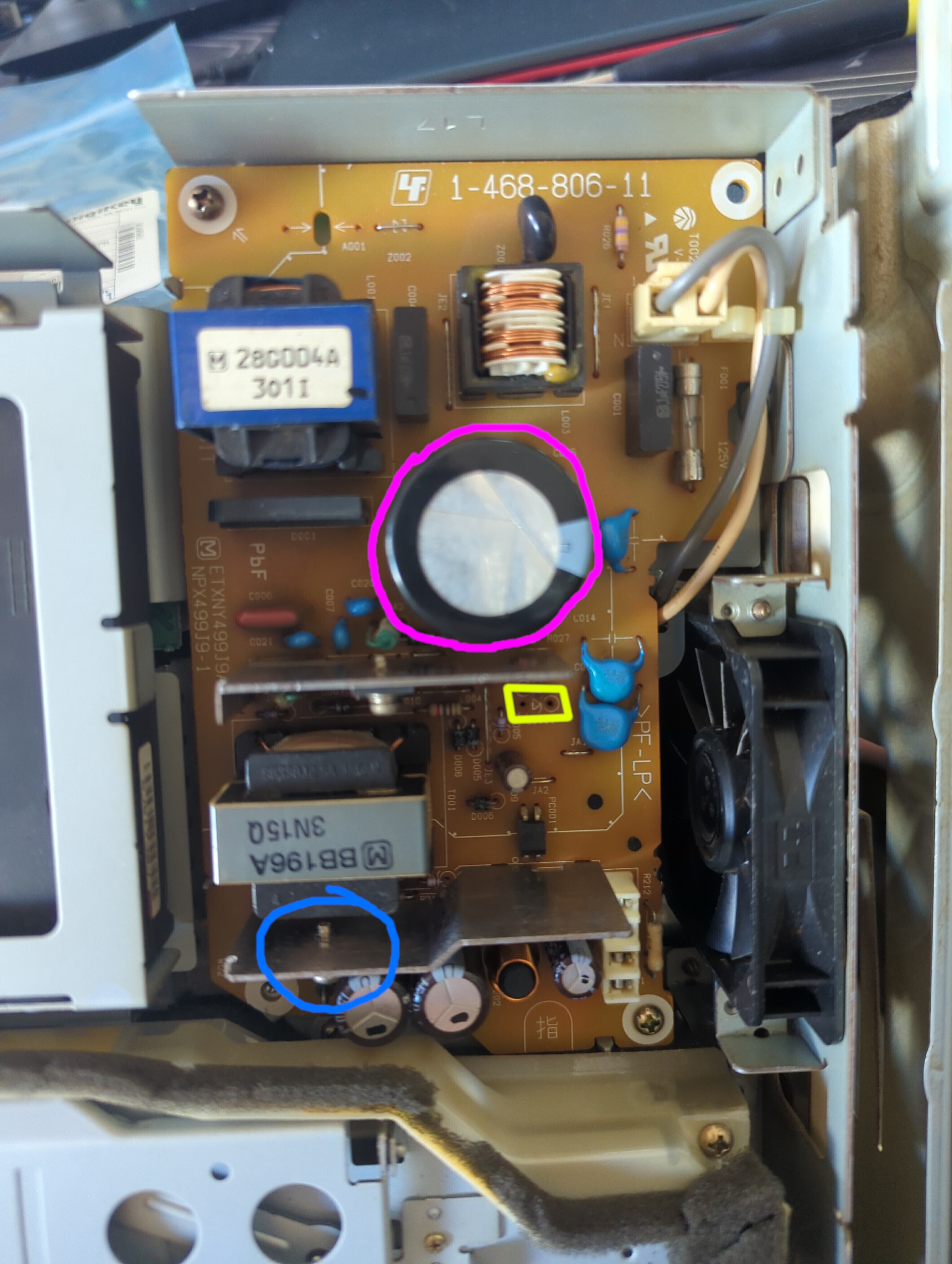
(bottom blue circle refers to the diode mounted to the heatsink)
- 1x Replacement Mains storage cap (C001) (Required) - circled in purple at the top.
- These store the initially converted AC -> DC power ready for the SMPS to cut it up.
- Type: Aluminium Electrolytic Radial
- Voltage: 400V Minimum
- Capacitance: 330μF or as high as you can get
- Diameter: 35mm Maximum
- Length / Height: 30mm Maximum
- Pin pitch: 10mm
- Pin type: Snap-in
- Temperature: 105℃ (Recommended)
- To locate replacements, set the above search terms, sort by price, then pick the capacitor that has a good balance of lifetime and ESR.
- I used a Rubycon 450MXK330MEFCSN30X30.
- 1x Replacement output "switching" diode (Recommended) - circled in blue at the bottom, mounted to the lower heat sink.
- This blocks the negative part of the AC coming out of the transformer, turning it into DC. The existing one is reportedly not quite capable of handling the increased voltage properly.
- Type: Schottky
- Reverse Voltage: 100V Minimum
- Forward Current: 10A Minimum
- Package: TO-220 or similar, Must have isolated tab
- You can use a dual-diode package, but the PSU only has holes for a single. Make sure that one of the two diodes in the pack has the 10A rating, some will mark themselves as 10A but they're really two 5A diodes.
- I used one Vishay MBRF10100-E3/4W.
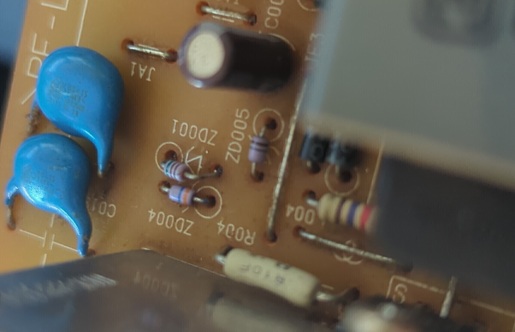
- We are also removing a diode (ZD001) that tells the PSU to shut down when the voltage is too high - it's shown in yellow.
Process:
- Disconnect the power from the PSX.
- Wait at least 30 minutes for the mains capacitors to discharge.
- Flip the console over.
- Remove both side rail covers by pulling in the (well hidden) locking tab while pushing them backwards.
- Remove the following screws:
- Remove the Two screws towards the front.
- Remove the Two screws in the back area of the bottom.
- Remove the Two screws in the "mezzanine" area near the ports.
- Remove the "mezzanine" cover and disconnect the ribbon cable. Be careful - the glue keeping the stiffening plastic to the cable seems to be failing.
- Flip the unit back up.
- Lift the top cover up and away from the unit. Note that there are some cables on the sides of the optical drive assembly that may get snagged when removing or installing the lid. This is particularly important on the PSX1 models.
- Remove the three screws holding in the power supply. The Power supply is the only board visible at this point, in the rear corner.
- Lift the power supply out. Note that the board does sit under some plastic for the optical drive, and the pins that connect the PSU to the main board may be quite tight. The power supply lifts directly up, once it's freed from the drive.
- Desolder the components we're removing:
- The big cap will pop out after some resistance.
- The switching diode is mounted to a heatsink, so it'd be advisable to unscrew it, or if you're feeling confident desolder the heatsink too.
- The small diode (ZD001) can be snipped, but I just used wick.
- Install the replacement parts:
- Solder the diode, making sure the line on the diode is the same side as the line on the diagram.
- Pop-in the input caps and then solder them. As with the diode, the line / negative symbol should be on the side with the thicker line on the part outline.
- Test the power supply.
- Attach your multimeter to the output, in 20V mode. The pins closest to corner of the board are negative, the other two positive.
- Safely connect the power supply to AC and turn it on. The multimeter should read 12V, or close to. If so, turn off the power supply.
- Next, attach your load to the power supply and turn it on again. If the power supply's voltage is stable, and close to 12V, then it should be good to go.
- Check the capacitors and heatsinks with the non-contact thermometer. They shouldn't be super warm (e.g. over 50 degC after a few seconds is too hot).
- Install the power supply in the PSX again - line up the pins and push the power supply onto them. You might need to angle the PSU to get it under the plastic before pushing it into the pins.
- Re-install the three screws into the PSU. These are the metal / machine-thread screws.
- Place the top on, reverse of the removal.
- Flip the unit.
- Connect the ribbon cable.
- Pop in the mezzanine cover.
- Re-install the two mezzanine screws, these are the only two that are different from the other bottom screws.
- Re-install the other four screws in the bottom.
- Re-install the plugs / feet that cover the screws.
- Slide your rails back on until the locking tab clicks.
- All done.